Double-pipe heat exchanger
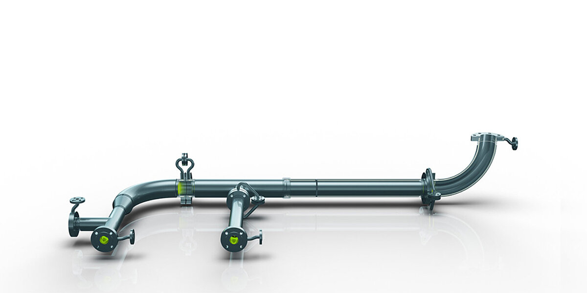
A typical heat exchanger design task is as follows: "We have a fluid A with a certain volume flow, which is to be heated or cooled from a certain inlet temperature to a certain outlet temperature. A second fluid B has a maximum flow rate of V and a certain inlet temperature. How must the heat exchanger be designed?".
The first and simplest method is to use analytical models. There are several analytical formulas for calculating the heat transfer coefficient or the design of the heat exchanger. But these formulas are based on certain idealized conditions, from which follows a design with large safety factors.

Task / Calculation
Computational fluid dynamics
With the aid of numerical computer models (CFD = computational fluid dynamics), the thermal design of heat exchangers can be optimized, taking into account the length and size of the heat-transferring surface, resulting in lower material costs. In addition, the flow parameters can be optimized, e.g. minimum flow rate of fluid B results in minimum energy consumption and reduced operating costs.
In the numerical simulation, liquids and solids can be modeled. In addition, general conditions can be taken into account, e.g. free convection. Together with the flow field (velocity and pressure) the temperature distribution can be solved in the model.
The physical models that can be used include heat conduction through the solids and fluids, energy transport by free or forced convection, and radiation effects. Since the heat transfer coefficient depends mainly on the velocity distribution of the fluid near the surface, the design of the heat exchanger can be optimized, for example, by influencing the flow field toward the maximum heat transfer coefficient.
Application example
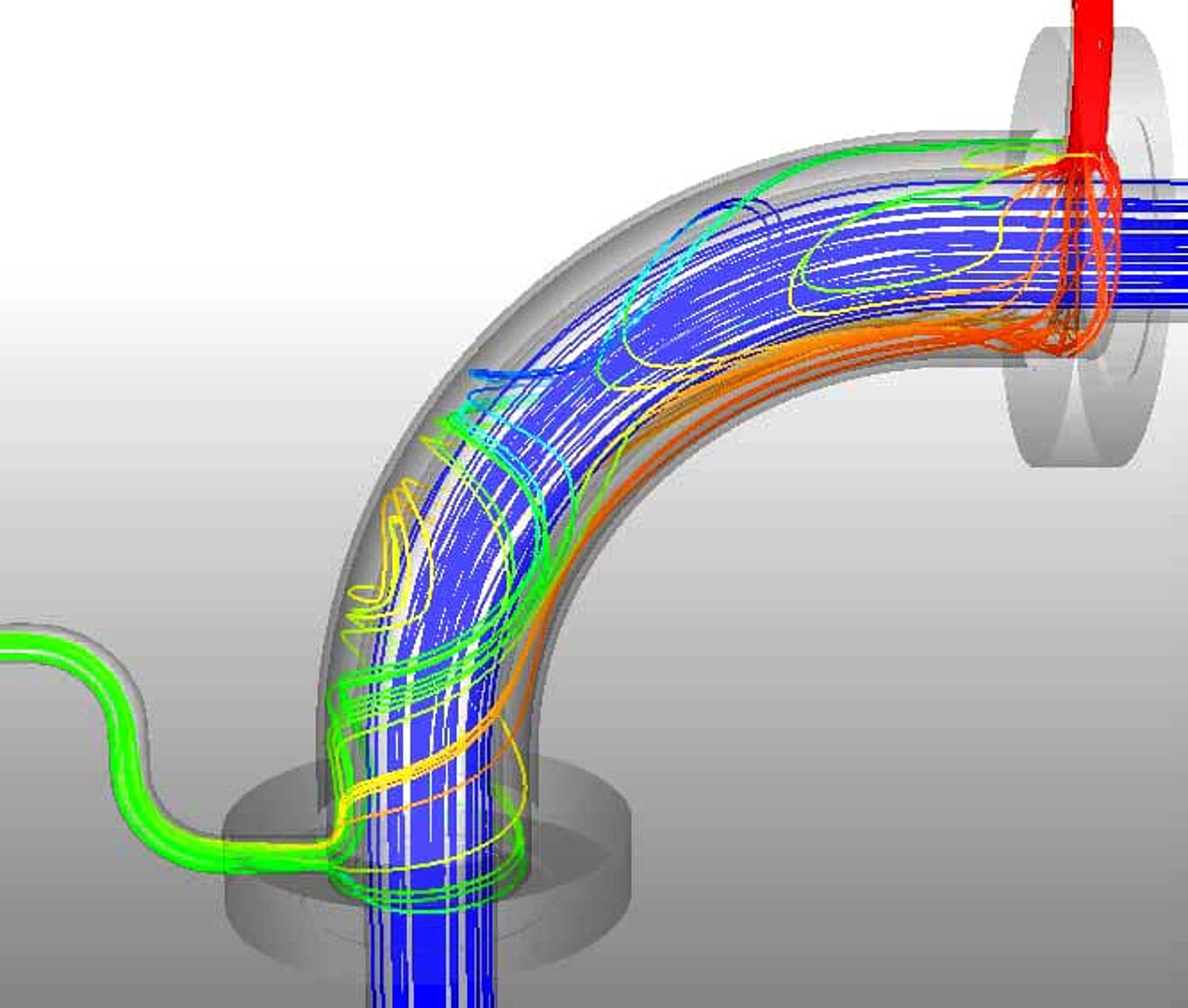
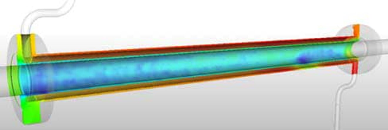
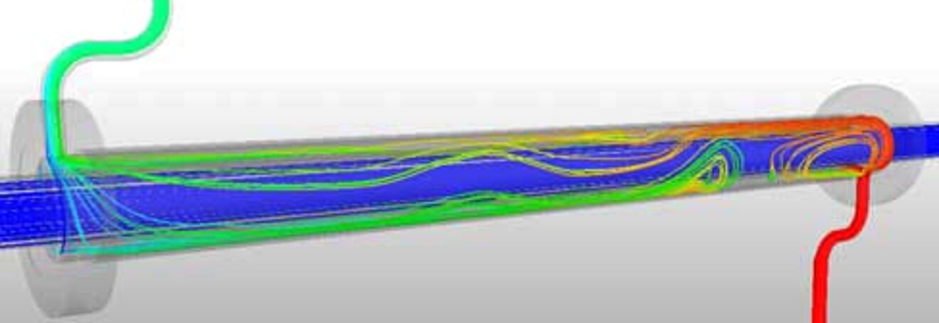
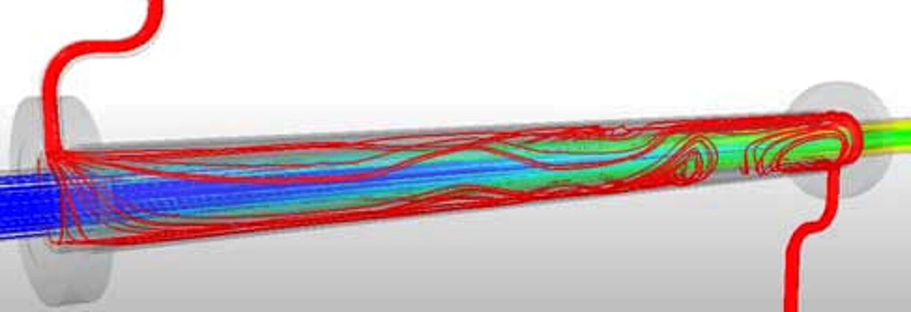
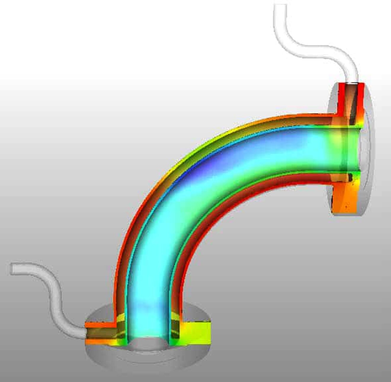
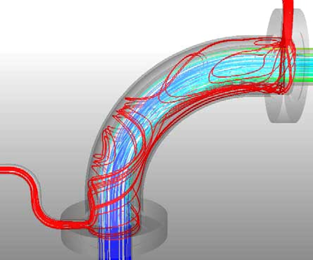
The two examples (see pictures below) show an excerpt of the results of a dummy model of the MHE33 and MHP23 double tube heat exchangers to demonstrate the possibilities of CFD simulation.
The colors indicate the resulting temperature distribution (red represents a high temperature, blue a low temperature). The environment was assumed to be air and free convection.
The results show that, for example, only 2% of the total heat flux is lost to the ambient air. The temperature rise of fluid A is at ΔT = 3K. However, the heat content of fluid B is reduced by only 0.3%, which could save a lot of energy.
With kind permission
MH Systems
