So that nothing hits the eye - simulations for optomechanical systems
![[Translate to English:] Header-Optomechanik-Sehtest [Translate to English:] Header-Optomechanik-Sehtest](/fileadmin/_processed_/7/0/csm_Header_Optomechanik_8d0de5fb9f.jpg)

Optomechanical systems are combinations of optical and mechanical components that are supplemented by electronic or electromechanical components for control and regulation.
Sounds complicated, but it is basically simple: your glasses are the lens system, your hand is the adjustment motor and your brain, which tells you that you can now see sharply, is the control electronics. To take the example even further, the heat in your belly from the previous evening's schnitzel is the power electronics that provide the energy and produce heat loss.
The field of application of optomechanical systems is manifold. From cameras and sensors to microscopes, measuring instruments and lithography optics, from telescopic sights on hunting rifles to target acquisition in tanks, ships, aircraft and drones. Space is not spared either; the eyes of satellites are high-precision optomechanical mirrors and camera systems, such as the Hubble Telescope.
The common factor is the required accuracy of optomechanical systems, which is negatively affected by the smallest disturbances.
The precision with which optical lenses are ground is of no use if the optical axes shift or twist due to internal and external influences during assembly or operation.
So what exactly hurts an optomechanical lens system? Especially a twisting of the axes in relation to each other is critical, while the axial alignment can often be corrected via the mechanics. In binoculars or a camera, the lens distance is changed in the axial direction (by turning the wheel) in order to focus. But if the axes tilt in relation to each other because the housing heats up on one side, there is hardly any way to compensate for this effect.
In our example: move the glasses axially, i.e. away from the eye, and then twist them. For all those who don't have glasses, steal one from the person next to you.
But how can it happen that the optical lenses no longer quite fit together?
The 3 mechanisms

There are essentially 3 mechanisms at work:
- Warpage during assembly
- Thermal distortion
- Deformation due to dead weight, acceleration, vibration or shock.
Depending on the application, one or the other side dominates.
In industrial measuring instruments or lithography, even the smallest temperature changes are critical. An optomechanical target optics in a tank, on the other hand, fights more against the rough shock conditions in the field (the blow to the back of the head when wearing glasses...).
A satellite's optomechanical camera system is exposed to great stress during rocket launch and has to cope with one-sided solar radiation in orbit. If a soldered joint comes loose due to vibrations during a rocket launch, this can result in space debris worth hundreds of millions of euros. It is not always possible to repair the Hubble telescope, which was simply fitted with eyeglasses. For this to happen, however, it has to be close to the Earth. A probe on its way to Mars will at least not find any known repair workshop on the way.
Let's take a closer look at the individual mechanisms.
Assembly
During the assembly of optomechanical systems, undesired strains can occur in the assembly due to screws, curing processes of adhesives or of potting compounds, which lead to a displacement of the optical axes (the frame is too narrow for your head).
This influence can be investigated and evaluated by an assembly simulation.
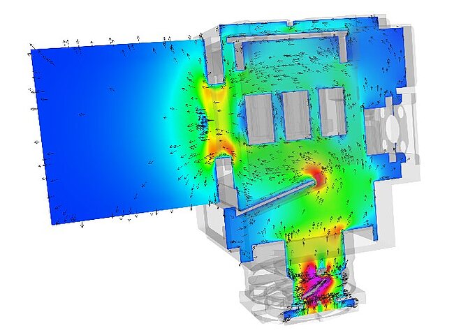
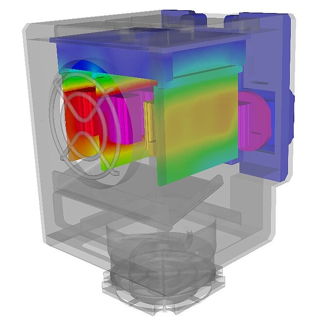
Simulation of the thermal distortion

Thermal distortion is caused by temperatures in the component. If an assembly consists of different materials (lenses made of glass, housing made of metal), it is sufficient to heat them evenly to cause distortion due to thermal expansion.
If the assembly heats up locally due to the power loss of the electronics or the servomotors of optomechanical systems or due to changes in the ambient conditions (solar radiation, ambient temperature) during operation, the optical defects change over time.
This thermal distortion can be simulated as stationary or transient, i.e. time-dependent.
Whether the temperature fields are calculated using FEM models or flow simulations is a question of the accuracy requirements.
The flow simulation method is usually more accurate, but also more time-consuming. You have to decide from case to case.
Here, unfortunately, my spectacle example is limping. If you have a fever, you see worse, but more because of the headache (control electronics) and less because of the thermal distortion. Unfortunately, you'll just have to take my word for it.
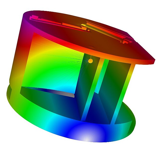
Static loads
Static loads are, for example, constant accelerations or the dead weight. The deformations are determined via an FEM simulation.
Since the glasses are very light, you probably see the difference less if you were to switch off the acceleration due to gravity, but it is there. Moreover, since very few astronauts fly to the moon with eyeglasses, the subjective comparison is missing.
Dynamic loads
Dynamic loads include oscillations, vibrations and shock.
These issues are simulated and evaluated in the FEM simulation.
A ride on a roller coaster quickly shows you what is meant here. The worst case scenario in this case is that your glasses fly off your head.
Further areas of application
In addition, there are other effects in optomechanical systems that can be investigated and evaluated via simulations. For example, the housings of laser optics are often filled with gases such as nitrogen or hydrogen. When evacuating and filling the housing, the smallest dust particles can scratch the lenses. Therefore, the maximum flow velocities must be kept in mind.
Back to our example: You are standing in a sandstorm with your glasses on.
You are welcome to get additional information on optomechanics and simulation on our homepage. The direct link is https://www.merkle-partner.de/en/optomechanical-systems
We are very familiar with all topics relevant to optomechanical systems and have the necessary methods, software packages and especially the know-how of 32 years of simulation calculation to help you, too, to develop better, more precise optomechanical components quickly and efficiently.
We are also familiar with the special requirements of simulation in the nanometre range, so you won't get any numerical "dirt" from us here.
Contact us for a non-binding discussion. We look forward to meeting you.
Your Stefan Merkle

PS: I wear glasses and am not an optician. If you have problems with your vision, you'd better go to your optician. If, on the other hand, your optomechanics have a bad vision, you've come to the right place.