Common design mistakes and how to avoid them #3

Generally applicable to a wide range of standards:
The strength verification of a component is divided into two steps:
- Static proof: Consideration of the maximum stresses.
- Dynamic proof: Consideration of the stress changes (stress amplitudes) during load changes.
Maximum stress and stress amplitudes are compared with respective allowable values.
Statically, the allowable stress value results from the yield strength or the tensile strength multiplied by a reduction factor.
Dynamically, the comparison value is the allowable stress amplitude, e.g. the flexural fatigue strength, multiplied by a reduction factor.
Bolted joints fail statically if the force leads to the static stress being exceeded. This is the case if, for example, the bolt is tightened too much or the load is too high for the bolt.
Dynamically, a bolt fails when the stress amplitude becomes too high.
A rule of thumb here is that the stress amplitude should be less than 40 N/mm².
Often, an incorrect bolt design only becomes apparent after a certain period of operation through bolt fractures.
One cause of bolt breakage may be that the bolt was designed too weakly for the acting loads. More often, however, the reason for bolt breakage is that the preload force has become lower. As a result, the stress amplitudes increase.
Causes for this can be, among others:
- Setting the screw
- Unscrewing
- Creep
- Clamping length too small
- Vibrations
- Temperature changes
The individual points are described in relevant standards and solutions are also suggested here. Basic considerations on bolted connections can be found, for example, at www.schrauben-lexikon.de/td3-werkstoffe-stahl.asp.
However, I frequently come across the following design error in cases of damage:
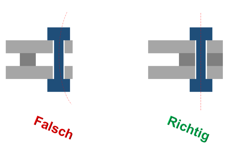
Although the bolted connection is designed for tensile and shear forces in accordance with the standards, it is additionally loaded by bending due to the design.
However, these additional bending stresses are not taken into account.
The following figure is intended to illustrate this case:
If the flange is very stiff, the bolt hardly sees any bending, but the thinner the flanges become, the higher the bending stresses become.
Usually, a bolted joint is designed in such a way that the pure prestressing force leads to a stress of 70% - 90% of the yield point.
If a bolt of strength class 8.8 is used as a basis, the yield point is about 640 N/mm².
However, if the flanges bend, the yield point is quickly exceeded due to the additional bending stress in the usual design, which only considers the normal force of the bolt. The bolt deforms plastically under one or more loads, the preload drops and the bolt sees higher stress amplitudes due to the reduced preload force. Thus, with alternating loads, the fatigue strength is reached very quickly and the bolt breaks.
These effects only become apparent when looked at in more detail, e.g. a finite element analysis. When this is considered in the context of a failure analysis, however, it is too late L
For standardized flange connections, it is often not possible to perform the strength verification when all relevant effects are considered in more detail. The reason why fewer problems occur here in reality is due to the usually low number of load cycles.
However, if this design principle is used for dynamically highly loaded components, e.g. a pump cover, unpleasant surprises are often encountered.
The principle that bolts should not be loaded by bending still applies.
If this is not possible otherwise due to the design, you should take a closer look at the stresses, e.g. using an FEM calculation.
I am looking forward to your feedback 🙂
Stefan Merkle
PS: In the video below you can see the FEM simulation of a bolted joint where no bending occurs because the flanges are on top of each other.

